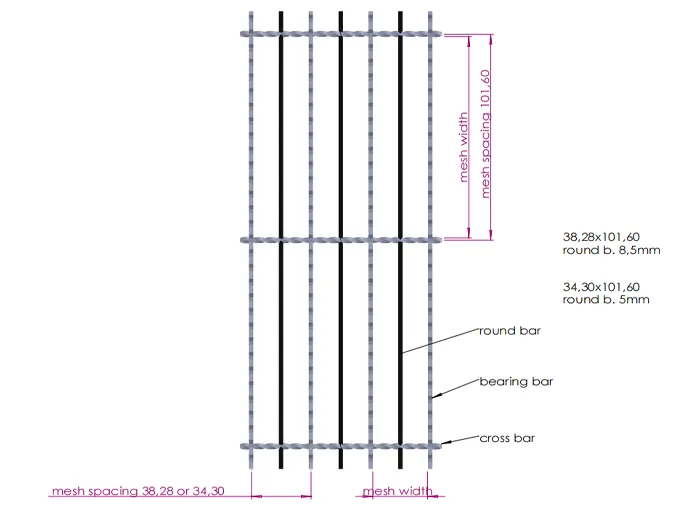
Structure specification diagram

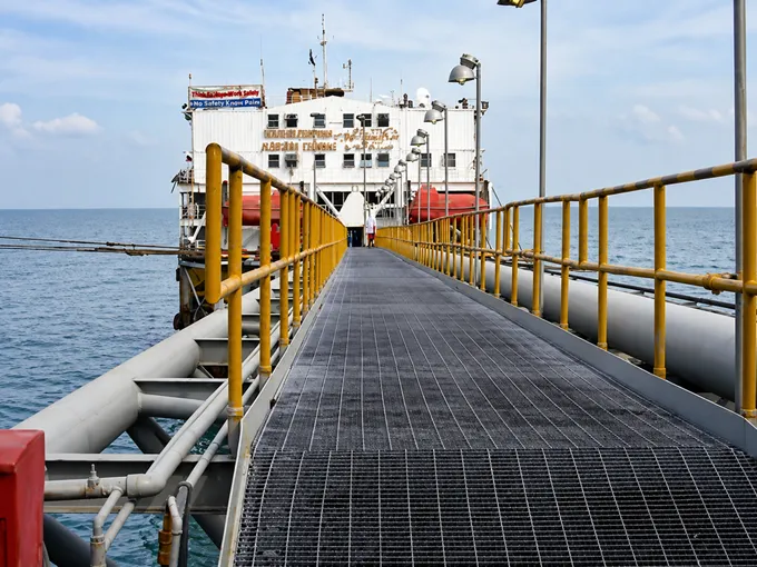
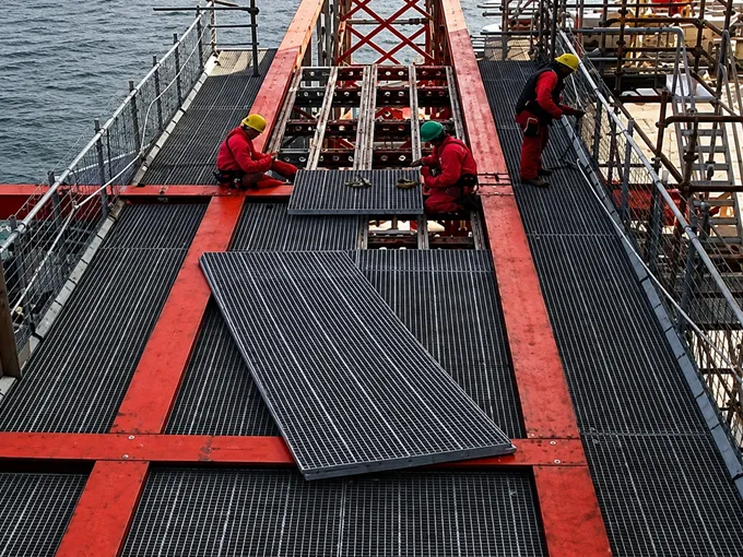
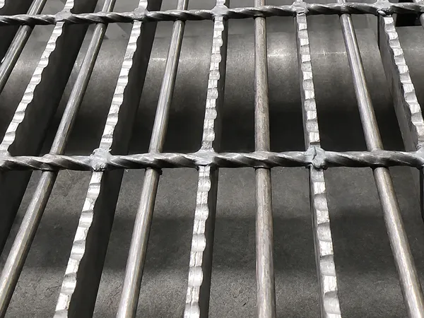
The offshore platform reinforced floor grating is a high-load grating solution designed for extreme marine environments and critical safety applications. As a reinforced version of standard offshore drilling platform grating, it features an additional round bar welded beneath the twisted cross bars and positioned parallel to the bearing bars. This reinforcement prevents 15 mm-diameter spheres and similarly sized objects from passing through the grating, improving personnel and equipment safety. With excellent corrosion resistance, anti-slip performance, high strength, and lightweight construction, the grating is widely used for offshore oil drilling platform floors, shipbuilding, and marine engineering projects.
Technical Specifications
Specifications & Standards
Our products comply with the O-SP-SS international standard, which was specifically developed for drilling platforms and shipbuilding applications.
| Parameter | Specifications |
|---|---|
| Material | S235 or S355 steel (equivalent to Q235B or Q355B) |
| Surface Treatment | Hot-dip galvanized, electro-galvanized, or painted; customizable |
| Manufacturing Process | Press-welded: twisted cross bars are pressed into bearing bars at 1000 kN and resistance-welded at 2500 kVA to form an integral structure |
| Bearing Bar Dimensions | Height: 25, 30, 35, 40, 45, 50 mm; thickness: 3, 4, 5 mm; serrated surface for slip resistance |
| Standard Mesh Spacing | 38.28 × 101.6 mm (bearing bar pitch × cross bar pitch); alternative: 34.3 × 101.6 mm |
| Reinforcement Round Bar | Welded beneath the cross bars, parallel to the bearing bars, preventing a 15 mm test ball from passing through |
| Banding (Edge Frame) | Flat bars typically matching the bearing bar cross-section |
| Standard Panel Size | 6100 × 1000 mm; custom cut sizes with re-edging on all sides |
Structure specification diagram
Load-Bearing Reference
The table below shows the maximum clear span for common bearing bar sizes under walking loads, based on a maximum deflection of 4 mm (L/200). Values are for preliminary design reference only.
| Bearing Bar Size | Weight (kg/m²) | Maximum Clear Span |
|---|---|---|
| 25 × 5 mm | 41.10 | 910 mm |
| 30 × 5 mm | 47.20 | 1115 mm |
| 35 × 5 mm | 53.30 | 1319 mm |
| 40 × 5 mm | 59.40 | 1523 mm |
| 45 × 5 mm | 65.50 | 1726 mm |
| 50 × 5 mm | 71.60 | 1928 mm |
| Note: Span values are based on standard load conditions; actual design should account for specific working conditions and appropriate safety factors. | ||
Available Grating Shapes
To meet different installation requirements, the grating is available in the following configurations:
Features
Applications
Marine access walkway
Offshore platform installation